
Click the following to view U.S. Cooler® Installation Guide. These plans will guide you through the steps of building / assembling your cooler or freezer unit.
U.S. Cooler Installation Manual
Click the following to view U.S. Cooler® Installation Guide. These plans will guide you through the steps of building / assembling your cooler or freezer unit.
U.S. Cooler Installation Manual
Once you have located the clear installation pack attached to the door, pull out the installation drawing for reference. Each panel is labeled with a C (Ceiling), W (Wall), or F (Floor) and a number. Separate the panels by grouping the C panels together, the W panels together, etc. Prior to installation, ensure there is proper clearance where box will be located. There should be a minimum 2” clearance around exterior of panels for airflow. Before setting panels, make sure there is proper clearance for door swing and Heated Pressure Relief.
Locate panels that are labeled letter F. These are floor panels. Using chalk line, measure out and mark floor for location of box. Lay the F1 floor panel in the location designated on the floor plan drawing (see figure 2). Take the F2 floor panel and fit male side of F1 panel into female side of F2 panel. Align both ends until they are even. Insert cam wrench into center hole on F1 panel. If hook is showing, back cam counter clockwise until you reach a stop, but do not force cam. Turn cam wrench clockwise until a solid stop is reached. Again, do not force past stop. Check to see if F1 and F2 floor panels are firmly attached together. If not, repeat this step. Otherwise, lock remaining cams and go to next panels until all floor panels are assembled. U.S. Cooler floors are not designed for the use of forklifts, pallet jacks, or hard wheeled carts. Damage caused by this usage will void the panel warranty.
The door threshold bar must be installed in the floor panel before the door is set in place where the door is to be located. With the hooks pointing in the same direction as the pins on the cam-locks in the floor, place the hooks of the threshold bar into the slots of the cams. Push the bar in the direction of the pin of the cam-lock until they contact. Gently tap the locking bar until it locks into the cams or quits moving. This movement is about 1 ½”. The locking bar is now installed. When the door is installed, screw the threshold down to the locking bar with the self-tapping screws provided in the install pack.
Using chalk line, mark location of box walls according to enclosed plans. Lay two beads of silicon caulk within the 4” wall location. Gray screeding can optionally be shot down with nails placed directly in the center of screeding. Put one bead of caulk on each inside edge of screeding.
Start with corner wall consisting of W1 and the adjacent wall panel that forms the corner. On floorless walk-ins, work panels into pre-installed screeding. On floored units, place male bottom of wall panel in female groove of floor panel. Make sure the floor arrow on the wall panel is pointing down. Once panel is inserted correctly, install W2 wall panel with W1 panel, male edge will be inserted into female edge of W2 panel. Special care should be given to ensure that top edges and sides of wall panels are flush. Take cam wrench and insert it into center hole of W1 panel. Be sure cam lock is set by first turning wrench in a counterclockwise direction until stop is felt. Do not force cam. After checking set of cam, turn wrench in a clockwise direction until stop is felt. Again, do not force cam. Check to see if panels are firmly locked together. If not, repeat this step. If they are, finish panel installation by locking all wall cams. Do not lock the panels to the floor until all wall and ceiling panels have been locked together. Continue installing wall panels by alternating from the lowest wall number to the highest wall number. On combination units, install center wall before continuing into cooler section. If the floor is uneven, adjustments must be made to ensure wall panels are flush at the top. When installing door panel, remove door by lifting door in an upward direction on panel and set aside until the frame is installed.
Doors on standard nominal units can be installed in any of the standard, full size wall panel locations, while custom built order units have fixed door locations. A door threshold hold down bar must be installed in the floor panel where the door is going to be installed. Place the hooks of the door threshold hold down bar, with the hooks going in the same direction of the cams, in to the slots on the cams. The hook on the bar should contact the pins in the cams. Gently tap the hold down bar in the direction of the cams and hooks until it quits moving, locking it in place with the cam hooks (approx. 1 ½”). Gap on handle side between the door & frame should be the same from top to bottom, and the gap across the top of the door, left to right should be equal. Continue installation of wall panels.
Check your drawing to locate where the door will be installed. 3 screws are provided to screw the threshold to the floor.
Angle brackets should be installed on exterior door legs using angle brackets and screws provided.
Risk of fire or electrical shock. Connect only to a grounded circuit protected by a ground fault circuit interrupter (GFCI). Failure to do so can result in death or serious injury.
Connect to incoming power source, via junction box, per local wiring codes.
Connect to incoming power source, via junction box, per local wiring codes.
1. Read all labels on unit and understand all risks.
2. Disconnect power at breaker.
3. Route all high voltage power (Line, Switched, Neutral, Indicator, and Three Way) through separate conduit than the temperature probe(s) and battery cable conduit. NOTE: Junction boxes must be rated for “Wet/Outdoor Location” if used in outdoor application Used Teflon/PTFE tape to wrap all thread conduit connections.
4. Connect power wires to terminal block. If wires fray while installing, it is required to tin (solder) the wire leads in order to press into terminal block. Do not allow stray wires to exit the terminal block.
5. Connect battery cable and temperature probe(s) on back of unit. Select Temperature Units with black jumper.
6. Push all wire into junction box. Secure to junction box with screw/washer. Must fully seat screw/washer and gasket.
Seal all conduit wire openings with a silicone sealant. This will keep moisture out of junction boxes.
Once wall panels are installed, proceed with C1 ceiling panel by placing it in location according to drawing. Align it so it is even on all edges. Many times uneven floors may cause ceiling to either be slightly bigger or smaller than wall panels. If this is the case, split the difference. All panels are made to allow adjustments due to varying installation conditions. Lock all cams according to previous instruction. After locking C1 panel, lift C2 panel into location so male side of C1 fits into female side of C2. Line up both ends and lock all cams. Continue installing ceiling panels from smallest number to largest number.
Drill and rivet ceiling support bracket to male or female cam. After brackets are riveted to female ceiling cams and ceiling is locked into place, bring male ceiling into place by lining the slot of the bracket up with the female slot and male lock. Wire cable must be hung straight up from the attached bracket to support beam. Bolts, washers, clamps and wire cable are supplied by others.
Stainless steel drip caps are supplied with outdoor walk-ins to reduce the amount of precipitation that would otherwise collect across the top and down the edges of the door. The drip cap is installed just above the door closer hook on the door frame. The 90 degree fold will be against the walk-in facing up. To install the drip cap, drill (3) 1/8” holes across the 90 degree fold and using the ½” long, pan head screws provided, attach the drip cap to the walk-in. To insure the drip cap is sealed tight against the walk-in, place a bead of silicone caulk either behind the fold when attached to the walk-in, or a bead of caulk along the top of the drip cap after attached.
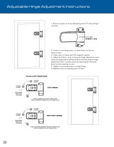
After all panels have been installed, close walk-in door. If the door does not shut correctly, verify that the reveal between the door and frame is even around the perimeter of the door. A reveal that increases or decreases across the top of the door, indicates one leg of the door frame is lower than the other and will need to be shimmed to correct the condition. The door and frame should be flush around the perimeter. If one corner of the door protrudes from the frame, it indicates that the bottom of one door leg is not aligned with the other leg and the frame has a slight twist. Unlock the cams around the perimeter of the frame and move the door leg in or out to correct the condition, then relock the cams. Once box is completely installed and door alignment is verified, screw the threshold down to the threshold bar on floored boxes and to the floor on floorless boxes with the stainless steel screws provided. On floorless units, attach L-shaped hold-down bracket to door legs and floor. Locate bracket on edge of door frame, small hole against the door leg, large hole to the floor. Install included Phillips self-tapping screw through small hole of bracket and into door leg. Install included concrete anchor through bracket and into floor.
Click on picture for larger version.
It is advisable, but not absolutely necessary, to caulk all joints inside the walk-in. This will provide for an even better-sealed unit. Use NSF-approved silicone caulking.
Install evaporator coil prior to rain roof installation and silicone caulking around the carriage bolt heads to avoid perforating the rain roof.
Install evaporator coil prior to rain roof installation and silicone caulking around the carriage bolt heads to avoid perforating the rain roof.
Slope foam installation for a walk-in consists of the tapered foam and the vapor barrier material. The slope foam taper typically starts at ¼” and goes up to about 4”. The foam is typically marked A,B,C,D, etc. depending on how many rows of foam are needed to cover the walk-in. Starting at a corner of the roof panel, place a row of panels down, depending on which direction the taper is made to run across the top of the walk-in. After each row is placed down, it’s always best to run a strip of furnace tape across the foam panel, just to keep them temporarily in place until the rain roof membrane has been installed. After installing all the tapered foam panels, we have provided a roll of 4 mil vapor barrier, that needs to be placed over the tapered foam panels. This protects the membrane from any gasses that may escape from the foam, which will reduce the life span of the membrane. With the foam and vapor barrier now in place, the roof membrane can now be installed.
For saddle mount and side mount units, set refrigeration system over notched wall panel with compressor mounted on outside of walkin. Drill through wall with 1/2’ drill bit and bolt unit on with provided bolts. If unit has top mount self-contained refrigeration system to be installed, place unit in prefabricated hole in top of walk-in with air flow marker pointing away from wall. Caulk around perimeter of refrigeration unit. All wall penetrations are required to have an airtight seal. All refrigeration components must be installed by a certified refrigeration contractor, who must be present at startup. Failure to do so may affect your warranty.